Thursday, April 21, 2011

Interfacing a motor

We cannot interface a DC motor directly with our micro-controller board as we will end up blowing up our board due to the back emf generated by the motor. As for robotics hobbyists, generally two types of DC motors are available in the market, a 12v or a 6v DC motor. Therefore driving a 6/12v device from a 5v micro-controller will lead to driving of a large amount of extra current from the device leading to burning up of its circuitry.In order to prevent the board from blowing up, we normally use an H-bridge to drive and control a motor from the micro-controller board. H-bridges use the direction of flow of current to drive and control a DC motor, as is shown in the figure below.But H-bridges suffer from the problem of complexity of the circuit.


Hence, in order to address this issue, L293D- a dual h-bridge motor driver IC was introduced. With one such IC, we can interface 2 DC motors which can be controlled in both clockwise and anticlockwise direction. Datasheet can be found here.
Just follow the schematic and the truth table shown below to interface a motor with L293D and you will be good to go.

Tuesday, April 12, 2011

A small tip for troubleshooting with sensors

One of the best way to detect the malfunctioning of sensors is to test them with Oscilloscope . Many times sensors don't gives desired output when interfaced with micro-controller. The use of oscilloscope gives you the correct voltage response against time. This will help you to select scaling factor of Voltage to make it work for 0-5V (required for most of micro-controller). In addition to this the frequency response of voltage will enable you to select best sampling rate for your ADC.

Friday, April 8, 2011

Resources for embedded hardware

This blog compiles all the sources (online as well as actual shops in Delhi) from where we procured our components:
  • Rhydolabz - http://www.rhydolabz.com/
    • Stuff Procured:
    1. 5 Amp Current Sensor - http://www.rhydolabz.com/index.php?main_page=product_info&products_id=506: Works nicely, sensitivity becomes a problem for measuring low current values
    2. RF (433 MHz) Transmitter
  • Lajpat Rai Market Shop Number 415 (Contact Person - Mr. Dhariwal, 9313544213)
    • Stuff Procured:
    1. 555 Timer Chip - Cost - Rs 30: Works nicely; Tried a version with 3.3V as well as 5V and was able to integrate both of them in my circuitry easily.

Thursday, March 31, 2011

Compiling TinyOS on Ubuntu Maverick (10.10)

  1. Ensure that you have uninstalled all the TinyOS related packages that you had previously installed. The following command should help:
    sudo apt-get --purge remove tinyos*
  2. Add the TinyOS repository to your sources.list (we will use the lucid packages since packages for maverick aren't available):
    echo "deb http://tinyos.stanford.edu/tinyos/dists/ubuntu lucid main" | sudo tee -a /etc/apt/sources.list
    sudo apt-get update
  3. Install the required TinyOS toolchain:
    sudo apt-get install tinyos-required-msp430
  4. Download the TinyOS source into ~/tinyos using SVN: 
    mkdir ~/tinyos
    cd ~/tinyos
    svn checkout http://tinyos-main.googlecode.com/svn/trunk/ tinyos-2.x
    Note: This does not work on the institute's internet due to certain blocking schemes.  If you're trying this from the institute's internet, download and extract this into ~/tinyos.
  5. Compile and install the tools:
    cd tinyos-2.x/tools
    ./Bootstrap
    ./configure --prefix=$HOME/tinyos/install
    make install
  6. Set the environment variables by adding the following to your ~/.bashrc:
    export PATH=$HOME/tinyos/install/bin:$PATH
    export TOSROOT=$HOME/tinyos/tinyos-2.x
    export TOSDIR=$TOSROOT/tos
    export MAKERULES=$TOSROOT/support/make/Makerules
    export CLASSPATH=$TOSROOT/support/sdk/java/tinyos.jar:.
    export PYTHONPATH=.:$TOSROOT/support/sdk/python:$PYTHONPATH
    export PATH=$HOME/tinyos/tinyos-2.x/support/sdk/c:$PATH
  7. Compile the Blink app to test:
    cd ~/tinyos/tinyos-2.x/apps/Blink
    make micaz sim

      Friday, February 18, 2011

      Accessing internal EEPROM on ATmega328P

      As we know, ATmega328P contains an internal EEPROM memory of 1KB in size. Since the internal EEPROM is a non-volatile memory, it can retain the stored information even after powering down the controller. In general, EEPROM is used to store any device specific parameters which will be read first to initialize external components after booting. This tutorial will explain how to write and read data on EPROM by giving an example code.

      What do we have on our plate?

      We can access the internal EEPROM using
      1. EEPROM library functions available in AVR-GCC.
      2. EEPROM access registers available in ATmega328P

      The first method is simple and straight forward by just calling the library functions available in eeprom.h. Whereas, the second method is slightly complicated by directly accessing the EEPROM's address/data/control registers and is preferred for time critical applications. I will explain both briefly.

      1. Using EEPROM library functions availabe in AVR-GCC
      AVR-GCC library provides set of library functions to access EEPROM. All interface functions are declared in avr/eeprom.h, and thus, we have to include this header in our code.

      Lets look at couple of functions which read and write a byte on EEPROM. Their prototype is as below.
      uint8_t eeprom_read_byte(const uint8_t * pAddress)
      Returns a byte of data read from address pAddress. 

      void eeprom_write_byte(uint8_t *pAddress, uint8_t value)
      Write a byte of data, value, at address pAddress.

      The documentation of full list of EEPROM access functions are listed here.
      The below example code demonstrates the use of few functions.

      /*
      * 328_eeprom.c
      * ATMega328P Internal EEPROM read/write
      * Created on: 20-Mar-2011
      * Author: samy
      */

      #define F_CPU 16000000UL
      #define BAUD 9600
      #define MYUBRR F_CPU/16/BAUD-1

      #include <stdio.h>
      #include <avr/io.h>
      #include <avr/eeprom.h>
      #include "delay_x.h"
      #include "USART328.c" /* Shared by Abhishek for USART interface */
      //#include <avr/sfr_defs.h>

      int main (void)
      {
      char buf[20];
      unsigned int addr;

      uint8_t rb8, wb8 = 'a';
      uint16_t rw16, ww16 = 12345;
      uint32_t rdw32, wdw32 = 1234567;
      float rfloat, wfloat = 123.45f;
      char rblk[5], wblk[5] = "abcd";

      USART_init(MYUBRR);

      for(;;) // Loop Forever
      {
      addr = 0;
      /* Read and Write a word */
      eeprom_write_word( (uint16_t*)addr, ww16 );
      rw16 = eeprom_read_word((uint16_t*)addr);
      sprintf( buf, "R/W %d @ %d\r\n", rw16, addr);
      USART_String(buf);

      /* Read and Write a double word */
      eeprom_write_dword( (uint32_t*)addr, wdw32 );
      rdw32 = eeprom_read_dword((uint32_t*)addr);
      sprintf( buf, "R/W %ld @ %d\r\n", rdw32, addr);
      USART_String(buf);

      /* Read and Write a float */
      eeprom_write_float( (float*)addr, wfloat );
      rfloat = eeprom_read_float((float*)addr);
      sprintf( buf, "R/W %d.%d @ %d\r\n", (int)rfloat, ((int)(rfloat*100))%100, addr);
      USART_String(buf);

      /* Read and Write a block */
      eeprom_write_block(wblk, (void*)addr, sizeof(wblk) );
      eeprom_read_block (rblk, (void*)addr, sizeof(wblk) );
      sprintf( buf, "R/W %s @ %d\r\n", rblk, addr);
      USART_String(buf);
      _delay_s(3);

      while( addr <= E2END ) /* E2END : last valid address in Internal EEPROM */
      {
      /* Read and Write a byte */
      eeprom_write_byte( (uint8_t*)addr, wb8 );
      rb8 = eeprom_read_byte((uint8_t*)addr);
      sprintf( buf, "R/W %c @ %d\r\n", rb8, addr);
      USART_String(buf);
      ++addr;
      }
      _delay_s(3);
      }
      }

      2. Using EEPROM access registers available in ATmega328P

      ATMega328P provides 3 registers to control the operation of EEPROM.
      1. Address Register (EEAR)
      2. Data Register (EEDR)
      3. Control Register (EECR)

      The below table explains the purpose and function of each register/bit.

      Name

      Length/Bit#

      Purpose/Function

      EEAR

      10(remaining 6bits unused)

      Address register. Contains EEPROM address to which data is read/written

      EEARH

      2 (Bits 0 to 1)

      Address high order bits

      EEARL

      8

      Address low order byte

      EEDR

      8

      Data register. Contains data to be read/written

      EECR

      6 (Bits 0 to 5)

      Control register.

      EEPM1

      EEPM0

      Bit 5

      Bit 4

      Together controls the programming mode.

      0 – Erase and write, 1 – Erase only, 2 – Write only, 3 - unused

      EERIE

      Bit 3

      Ready Interrupt Enable

      1 – Enable Ready interrupt, 0 – Disables

      EEMPE

      Bit 2

      Master Write Enable. Must be set to one to write and will be reset after 4 clock cycles.

      EEPE

      Bit 1

      Write Enable. When set to one, writes the content of EEDR at EEPROM address EEAR. EEMPE must be set to one.

      EERE

      Bit 0

      Read Enable. When set to one, trigger the Read operation. Reads the data at address EEAR and store to EEDR.

      More detailed information such as number of clock cycles for each operation, interrupt controlled EEPROM access, etc are explained in the datasheet.
      Below is the implementation of simple read/write operation for a byte and string. These functions can be interfaced with above code. Also, please note that these functions assume interrupts are disabled, if not, you have to call cli() function (clear global interrupt mask in avr/interrupt.h) first before invoking any one of the below functions.
      void eeprom_write_byte1(uint16_t addr, uint8_t data)
      {
      while(EECR & (1<<EEPE)) /*wait until previous write any*/
      ;
      EEAR = addr;
      EEDR = data;
      EECR |= (1<<EEMPE);
      EECR |= (1<<EEPE);
      }

      uint8_t eeprom_read_byte1(uint16_t addr)
      {
      while(EECR & (1<<EEPE))/*wait until previous write any*/
      ;
      EEAR = addr;
      EECR |= (1<<EERE);
      return EEDR;
      }

      /*assumes s is a proper null terminated string*/
      void eeprom_write_string(uint16_t addr, char *s)
      {
      while(*s)
      {
      eeprom_write_byte1(addr, *s );
      ++s;
      ++addr;
      }
      }

      /* read a string of len characters maximum starting at addr.
      * modify according to your need!
      */
      void eeprom_read_string(uint16_t addr, char *s, int len)
      {
      while(len)
      {
      *s = eeprom_read_byte1(addr);
      if( *s == '\0' )
      return;
      --len;
      ++s;
      }
      *s = '\0';
      return;
      }
      References:

      Wednesday, January 26, 2011

      Synchronization Problem while burning the code

      I got a avrdude: stk500_getsync(): not in sync error while uploading the code to the micro-controller using avrdude. I tried different ways like changing the com port, reconnecting the USB cable as suggested by our TA but it didn't work for me.

      Finally, i realised that the problems comes up when i try to burn the code with LCD connected to the respective pins . So, i tried with removing the LCD connectors during uploading the code and it worked out fine . This piece of text can help if others are facing such problem.

      Do not let the connecting cables to touch each other. This can blow up the main IC.

      Tuesday, January 25, 2011

      LCD doubt

      While I was making the program for LCD I figured out that the accuracy of LCD is pretty low. If I make the program dispaly "tanmay" it shows "vounmay" and for "abcd" it was showing "abcd" in one blink and "afgf" in another and also random charcters some time. Has anyone else also been experiencing something and what could be the possible error?

      Saturday, January 22, 2011

      Another possibility for Coding Purposes

      There is another development platform known as "Arduino" :-
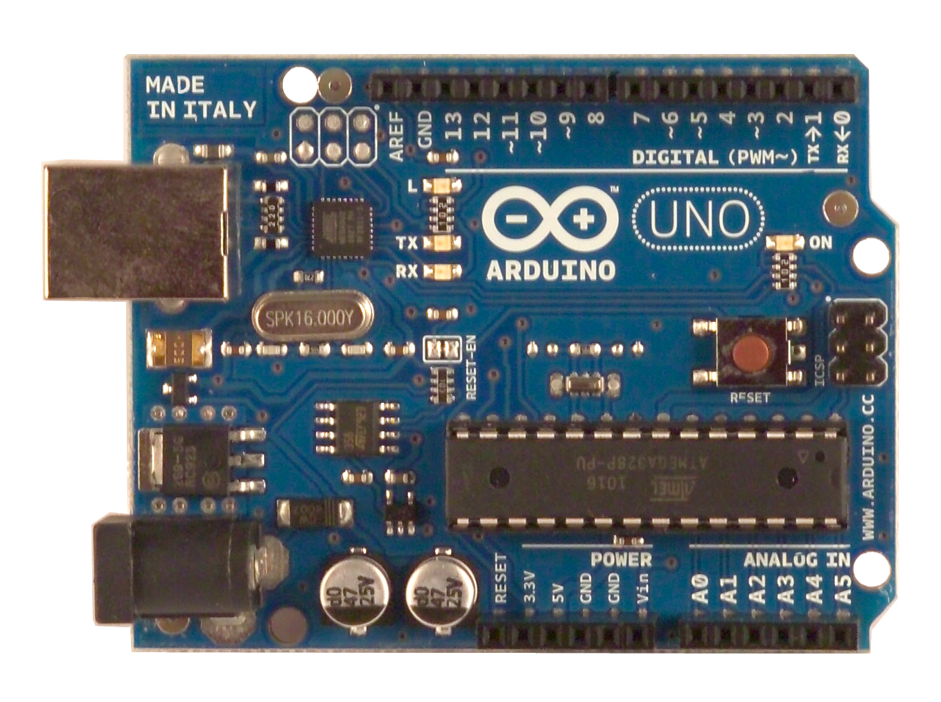
      "Arduino is an open-source electronics prototyping platform based on flexible, easy-to-use hardware and software. It's intended for artists, designers, hobbyists, and anyone interested in creating interactive objects or environments." quoted from the homepage...


      This development platform is fully supported by our boards, has a good community support, very simple and precise syntax, inbuilt functions for majority of operations, awesome library support, support on all types of operating systems.
      This platform functions on the basis of Pin Numbers and not Ports, and thus reduces the syntax quite considerably.

      This platform has an IDE for its own, whose installations instructions can be found here. The latest version of IDE is 0022, which is still alpha for windows but is quite stable on linux.
      The IDE is only about 3.5MB for linux, whereas it is about 180MB in windows as the developers provide all the packages consisting of all the pre-requisites as well.
      Though i haven't tried the IDE on windows, because of the same reasons Arjun explained in his post, for linux, there are a few pre-requisites, namely being pre-installed JVM, gcc-avr, avr-libc and avrdude, installation is done by :-

      sudo apt-get install gcc-avr avr-libc avrdude arduino arduino-core

      I am assuming that JVM is already installed and all repositories are pre-selected. For more help, one may refer here.

      The IDE is only about 3.5MB for linux, whereas it is about 180MB in windows as the developers provide all the packages consisting of all the pre-requisites as well.

      Numerous examples are already available, which are accessible from the IDE itself and burning the code onto the board is also very simple(just click of a button) once the IDE has been correctly configured

      Arduino version of the practical done on Thursday's lab session is as follows :-

      "void setup() {
      // initialize the digital pin as an output.
      // Pin 13 has an LED connected on most Arduino boards:
      pinMode(13, OUTPUT);
      }

      void loop() {
      digitalWrite(13, HIGH); // set the LED on
      delay(1000); // wait for a second
      digitalWrite(13, LOW); // set the LED off
      delay(1000); // wait for a second
      } "

      Yes, thats it !!! No need of including headers and other stuff, just write this on the IDE, compile/verify the code and upload onto the board.

      Friday, January 21, 2011

      Compiling and burning code for AVR ATmega328P on Linux

      I know most of you here would prefer developing on Windows, since that's the environment you're most comfortable in, but for me, booting into Windows meant three things:
      1. Loss of my awesome uptime on Linux (You don't get to six days of uptime without making a few enemies)
      2. Venturing into an unfamiliar territory 
      3. Loss of productivity. Games.
      Therefore, I decided that I will setup my development environment on Linux.

      What you will need:
      • gcc-avr - compiler
      • avr-libc - standard AVR C library
      • avrdude - burner
      • simulavr - simulator
      • vim (or any other editor) - for, you know, stuff.
      To install all of them together, do:
      sudo apt-get install gcc-avr avr-libc avrdude simulavr
      Note that you do not need the FTDI driver, since FTDI support is built into the Linux kernel


      The environment:
      We will use vim for writing the code. Let's start with something we did in Thursday's lab:
      #define F_CPU 16000000UL
      #include <avr/io.h>
      #include "delay_x.h"
      
      int main() {
        DDRD = 0x20;
        while (1) {
          PORTD |= 0x20;
          _delay_ms(100);
          PORTD &= ~0x20;
          _delay_ms(100);
        }
      }
      Write the code to a file (say, leds.c) and then compile it using avr-gcc. We need to tell avr-gcc what CPU to compile for. The entire command looks like this:
      avr-gcc -mmcpu=atmega328p leds.c -o leds.out
      Now we need to create a hex file containing the .text and .data part of the object to burn onto the board. We will use avr-objcopy for this.
      avr-objcopy -j .text -j .data -O ihex leds.out leds.hex
      Great! Now that we have the hex file, let's burn it onto the board. We're gonna use AVRDUDE for this. We need to specify the port (which you can see by running "demsg | tail" after you plug in the board), the baudrate (57600 is good), the programmer (m328p), and the programmer ID (let's use AVRISP). The complete command will be:
      sudo avrdude -P /dev/ttyUSB0 -b 57600 -p m328p -c AVRISP -F -e -U flash:w:leds.hex
      Great! Now you've burnt this program onto the board! Test it out by connecting the LED's red wire to pin 5, and yellow wire to ground.

      I hope this will help the minority which wants to program the AVR board on Linux. Good luck!

      PS: There's an easy way. You could use this Makefile to automate the tasks.

      PPS: There's an even easier way. Just install the AVR plugin for Eclipse. It does everything for you.

      Constructive criticism welcome.

      Sunday, January 2, 2011

      Welcome to the Introduction to Embedded Systems Course, IIITD, 2010

      Dear friends

      Welcome to the course on Introduction to Embedded Systems for Winter 2011. I hope that you will get exposure to basic functionality of a microcontroller and its interfaces as well as understand how such a simple (and cheap!) device can be used for doing smart things around you. We will use this space to follow up with discussions related to the course that may include - interesting articles, doubts you want to be clarified by your peers and other related discussions.

      Some protocols for posting on the blog:

      1. Has to be more than 80% of your own content: Rewording whatever is out there somewhere does not count as your own content 
      2. Whatever you copy has to have the appropriate reference 
      3. Write the complete rough draft and read through it to make sure you understand it yourself before publishing the post 
        • Make sure you understand what you are writing and don’t just publish something for the sake of doing it
      Hope you will enjoy the course as well as this online space for discussions related to the course.